Building a Model of an Iroquois Longhouse
TABLE OF CONTENTS
- DRAWING PLANS FOR A LONGHOUSE
- Scale
- Floor Plan
- Cross Section or End View
- Longitudinal Section or Side View
- Floor Plan
- READYMADE PLANS FOR A LONGHOUSE MODEL
- List of Materials for One Compartment of a Longhouse Model
- Step by Step Assembly
- Step by Step Assembly
LIST OF ILLUSTRATIONS
Figure 1. Longhouse model: Floor plan for one compartment.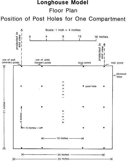
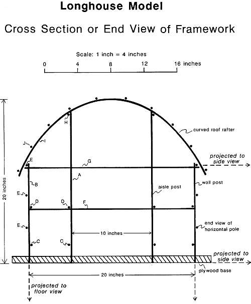
Figure 2. Longhouse model: Cross section of framework.
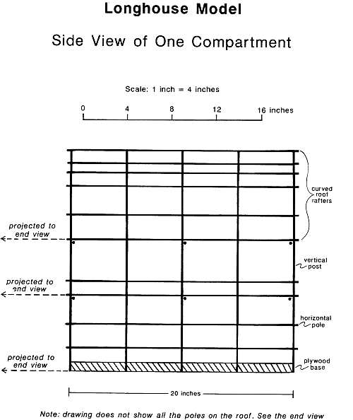
Figure 3. Longhouse model: Side view of one compartment.
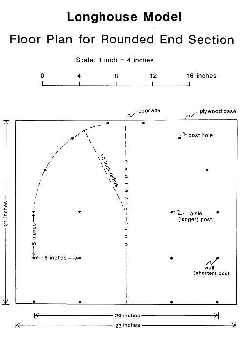
Figure 4. Longhouse model: Floor plan for rounded end.
Figure 5. Tearing cloth tape into strips.
Figure 6. Sketch of framework parts.
BUILDING A MODEL OF AN IROQUOIS LONGHOUSE
Building a model or a full sized structure requires plans, a list of materials, and a set of procedures to follow in construction. You might create these yourself from your knowledge of the desired structure, or you can use plans prepared by someone else. Suggestions for both approaches are provided here.
From your knowledge of how an Iroquois longhouse looked and how it was made, you can draw plans for building one. Plans for a building will show three views: a floor plan, which shows how things are arranged when viewed from above; a cross section, which shows the structure when viewed from the end; and a longitudinal section which is a view from the side. The plans should be drawn to scale, so that all things appear to be the right size when compared to each other. The same components appear in all three views, but may have a different appearance from one view to another, because of the viewing direction.
The scale of a drawing or model indicates how big it is when compared to the actual object. If plans for a building were drawn at the scale of 1 inch = 4 feet, that means, for example, that a post shown to be one-inch long on the drawing would be 4 feet (48 inches) long in the building. The scale can be written as 1 inch = 4 feet or 1 inch = 48 inches or 1:48, all are different ways of saying the same thing. The ratio 1:48 lets you use any measuring device you wish during construction. For example, with a metric ruler, 1 centimeter on the plan would represent 48 centimeters on the building. The scale ratio can be considered as a fraction; in this case it indicates that a distance on the plan is 1/48th the corresponding distance on the full sized building.
If the plans are drawn at the scale of 1 inch = 4 feet, the longhouse will be five inches wide on the drawing. (Assuming that the longhouse will be 20 feet wide and 20 feet high: 20 feet x 12 = 240 inches\48 = 5 inches). Using graph paper with 4 squares to the inch, may make the drawing easier; each square on the graph paper will represent one foot in the longhouse.
Draw a floor plan for one 20-foot-long section of a longhouse according to the descriptions you have read. (During construction this section can be replicated until the building reaches the desired length). A floor plan will show where each post should be placed in the ground. Remember that the posts and other framing have to support the bark sheets that cover the structure so they have to be close enough together for that. Assume that you can get the bark in pieces at least five feet long. Show where people will sleep, and where the cooking will be done, and storage closets. Label the distance between parts at full size; for instance the width of the longhouse would be labeled 20 feet.
Draw a cross section of the longhouse. This is a view of what you would see if you cut through the building as though you were slicing a loaf of bread. A slice is a cross section. The drawing should show the outside wall posts, the interior aisle posts, poles running across the structure to tie the posts together, the rafters that arch across the top to support the roof. The central aisle and the family living areas to the sides will be in the spaces between the posts. This view should show the ends of the poles that run along the length of the longhouse.
Longitudinal Section or Side View.
This view will show the poles that run along the length of the structure and tie the cross sections together. Draw a view of the side of the compartment as it would appear if viewed by a person standing in the center aisle. (Imagine cutting a loaf of bread in half lengthwise). Show the vertical posts and the horizontal poles that tie the posts together, making a grid pattern. There should be some horizontal poles to tie the roof rafters together as well. This view should show the ends of the poles that run across the width of the structure.
BUILDING A MODEL FROM YOUR PLANS
After the plans are completed, think about building a model from them, rather than using the plans supplied in this booklet. This will bring out problems not foreseen while developing the plans and provide the chance to work them out. Completing a building (models included) from a design of one's own creation, is a satisfying experience.
The first decision must be the size that the finished model will be; that is, one must determine its scale. One common scale for such model buildings is the "dollhouse" scale, one inch = one foot, or 1:12; a model of a 200-foot-long structure would be 200 inches long. This makes a large tabletop model and has the great advantage of being large enough to make assembling the parts relatively easy. A larger model at the scale of 1:4 would be five feet high and five feet wide (assuming full size is 20 x 20 feet; 1/4 x 20 = 5). You might build one like this outside.
After the size of the model is established, a list of materials should be prepared.
READYMADE PLANS FOR A LONGHOUSE MODEL
These plans are offered for those who want to go directly into assembling a model without the preliminary design work. These plans intend that the construction of the model will simulate some of the Iroquois methods and materials of construction, for example, lashing the framework together, rather than using glue, bolts or nails. The design assumes that the 'bark' covering material will be available in 5-6 foot sheets, which controls the spacing of the framework members. Bark sheets of this size probably were readily available to Iroquois builders.
The scale chosen is the 'dollhouse' scale, one inch = one foot. This creates a structure that is large enough to work on with relative ease: the framework members are far enough apart so that the joints of the framework can be lashed by hand. A smaller scale would require much more dexterity. The plans call for modular construction: because the interior of the Iroquois longhouse was subdivided into a series of identical compartments, these plans show the construction details for only one compartment. Any number of individual modules can be set end to end to create a longhouse. A floor plan for a rounded end is included.
Note. These plans are shown at the scale of one inch = four inches or 1:4 because they are for a model, not a full sized building.
Figure 1. Longhouse model: Floor plan for one compartment.Figure 2. Longhouse model: Cross section of framework.
Figure 3. Longhouse model: Side view of one compartment.
Figure 4. Longhouse model: Floor plan for rounded end.
List of Materials for One Compartment of a Longhouse Model
| Purpose | Material | Number |
| Base | 21 x 23 x 3/4" plywood (AC grade) or 1/2" Medex, fine-grained particle board. (Styrofoam board not recommended) | 1 ea. |
| Framework | Slender branches, 1/2 -1/4" in diameter, 2-4 feet long | 3 - 4 dozen |
| or | ||
| Framework |
|
|
| XX | ||
| External battens | Slender branches, 1/4" in diameter, 2-4 feet long | 2 dozen |
| or | ||
| External battens | Wooden dowels, 1/8 x 48" - 10 ea. or substitute #4 round reed for roof battens - 5 pieces x 36" - and get four fewer 1/8th inch dowels | |
| XX | ||
| Roofing and siding | Heavy paper, corrugated paper, corn husks, etc. | |
| Benches and shelves | Cardboard, heavy paper, bark, etc. | |
Notes on materials
Base. Holes drilled into the base that receive the posts simulate the holes in the earth the Iroquois would have used. The 3/4" plywood gives good support during construction when the posts are wracked back and forth a lot while the poles are being lashed to them. Styrofoam, being soft, probably won't hold up well under this stress. Medex, a fine-grained composition board, is smooth and flat and fairly sturdy. It may cost less than plywood. Try the one-half inch thickness, if available; 3/4-inch is fine, too.
Framework. If using dowel rod, be sure to get those that are 48 inches long, rather than 36 inches. If using natural twigs, these should be long, slender, fairly straight sticks or branches. Shrub varieties of dogwood work well, especially red-osier dogwood (Cornus stolonifera), commonly called "red willow." This shrub prefers moist soil and may form thickets along stream banks. Good stands of it exist in the field, but may be hard to find in your area. Any straight shoots or branches will do. Thin ones are best for the curved roof rafters. They bend more easily when freshly cut. Fresh sticks are easily pared down to fit into the post holes drilled in the base.
Round reed, available at craft stores with the chair-caning and basketry supplies, comes in a variety of weights. It might be used for the curved roof rafters and the horizontal poles on round end sections. Soaking in water for a few minutes, makes it work more easily.
Lashing. Cloth adhesive tape is probably the best lashing material, especially for the younger builders. The sticky surface makes it stay put while work is in progress. Cloth sports tape costs less than the first aid type and works well. The best tape, because it tears so nicely, is gaffers' tape, available from video or theater supply houses; it comes in 2-inch x 60-yard rolls; it is commonly black. Brown gaffers' tape exists, but it may require a special order.
Each compartment requires at least a 10-yard roll of tape, 1 1/2" wide. Tear the tape into narrow strips (1/4") about 12 inches long. Figure 5 shows a technique for tearing the strips.
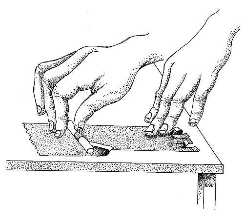
Figure 5. Tearing cloth tape into strips.
With scissors, split the tape at one end into six strips for 1 1/2-inch tape, eight strips for 2 inch. Put a piece on
the table, and tear a strip a short way, winding it on a short stick as you go. Hold the tape on the table with
one hand as you tear with the other. Tear away from you, rather than pulling up. Having the tape wound on
the stick makes it much easier to handle while lashing the parts together.
String works well as lashing; it is a bit more difficult to use than tape. Use the soft, general purpose, single strand type. Waxing the string before use makes it stay in place little better. Waxed dental floss will also serve.
Roofing and Siding. Heavy paper can be wet, wadded up, and smoothed out to dry. This gives it some texture to simulate bark. Pieces of corrugated cardboard boxes soaked in water can be separated into three layers. These work well for siding and benches.
Consult the plans to find the lengths of the framework pieces. (If you drew plans for a full sized longhouse at a scale of 1 inch = 4 feet, that will convert to 1 inch = 4 inches for this model.) The plans included herein (Figures 1, 2, 3 and 4) were drawn for a model, not a full- sized building; the scale is 1: 4, that is, 1 inch on the plan should represent 4 inches on the model. Measure the length of a post or pole on the plan and multiply that dimension by 4 to get the length the part should be for the model. For example, if the length of a wall post is 3 inches on the plan, this post should be 12 inches long in the model. This represents 12 feet in a full- sized longhouse. Beware: these plans have been duplicated with electronic devices, which sometimes changes the scale of such graphics. To measure dimensions directly from these plans, verify the measurements with the bar scale on each drawing, and accommodate any scale change before cutting parts.
1. The base
- Refer to the floor plans for the correct posthole spacing, then layout the position of the postholes on the base.
- Drill postholes through the base. Use a drill bit of appropriate size; it depends on the materials available for the posts. We use a 5/16-inch diameter drill bit, 3/8-inch works also.
- Paint the base brown to simulate the earthen floor. This will be much easier to do before construction is started.
2. Prepare the posts (parts A and B on Figure 6 and Figure 2).
- Wall posts should be 3 inches on plan; cut them 12 inches long; 10 required.
- Aisle posts should be 4 5/8 inches on plan; cut them 18 1/2 inches long; 10 required.
- If using dowels, they should fit the postholes. We use 5/16-inch diameter dowels.
3. Setting the posts into the base
- Trim the ends of sticks to fit the postholes.
- The taller posts (A) define the central aisle, the shorter ones (B) are for the walls.
- Tap the post through the base, so that the tops are even.
4. The bench-support poles (parts C on Figures 6 & 2). (1/4 inch dowels).
- Use the shorter edge of the base to measure these poles and cut them (21 inches). 4 required.
- The plan shows the height these poles should be above the base; mark that position on the posts (1 1/2 inches above the base)
- Lash the poles in place; make sure they are on the correct side of the posts: inside the wall posts and outside the aisle posts, so that they will support the edges of the bench without interference from the posts. Check the cross-section view of the plan for correct position.
- Keep the posts vertical as you tie things together.
5. Shelf-support poles (parts D on Figures 6 & 2). (1/4 inch dowels).
- These are cut and installed in the same way as the bench supports. 4 required.
- Remember to keep the posts vertical as you lash.
6. Wall poles (parts E on Figures 6 & 2). (3/16 inch dowels)
- Measure and cut these in the same way you have other poles. 6 required.
- Lash them to the outside of the wall posts, three on each wall, evenly spaced.
- Lash the top one as close to the top of the posts as possible.
7. Lower cross poles (parts F on Figures 6 & 2). (1/4 inch dowels)
- To gauge its length, lay a pole from one wall post across the model to the opposite wall post; cut the pole an inch longer to allow 1/2 inch on each end for lashing (21 inches). 3 required.
- Install the first pole across the middle set of posts; position it under the shelf-support poles.
- Check the cross-section view and Figure 6 for proper position.
- Lash the pole to every post it crosses.
- Keep the posts vertical as you lash things together.
- Install the other two poles in the same way across the posts at both ends of the compartment.
8. Upper cross poles (parts G on Figures 6 & 2). (1/4 inch dowels)
- Repeat the procedures of step 7. (21 inches) 3 required.
- Install these cross poles under the topmost wall poles.
9. Rafter-support poles (parts H on Figures 6 & 2). (1/4 inch dowels)
- Measure and cut these poles in the same way as you have other longitudinal poles (21 inches). Two required.
- Install one near the top of each row of aisle posts, toward the outside of the building.
- Lash these poles as close to the top of the posts as possible.
10. Curved roof rafters (parts I on Figures 6 & 2). (1/8 inch dowels)
- Bend a long slender stick across the top of the model to gauge the length; leave more than an inch overhang at each side for overhanging eaves.
- Cut this stick to length; use it as a gauge stick for the other rafters. 5 required
- Lash the first rafter across the model at the center, starting at the top of the aisle posts; place it so the overhang is even on both sides; it should be curved evenly over the high point of the arch.
- Lash the other four rafters at the top of each set of posts; make sure they are all the same height at the top of the arch so the roof will be even.
11. Roof poles (part J on Figure 6 & 2). (1/8 inch dowels)
- Measure and cut these in the same way as you have the other longitudinal poles. 10 required.
- Space them evenly across the entire arc of the roof; see the cross section view of the plans.
- On each side, one of these poles will be lashed near the ends of the curved roof rafters to form the eaves. Don't place this pole at the very end of the rafters, but let the rafters extend beyond it a bit so roof battens can be tied to them later.
12. Benches, shelves, and partitions
- Cut sheet material for the benches and shelves to fit. Lay some short poles across the width of the benches for support, if necessary.
- Prepare vertical partitions and lash in place. Add pieces of framework as needed.
13. Siding and roofing (cover only half the structure, so the interior is accessible from one side to allow furnishings to be installed).
- Siding is hung from the horizontal poles that are on the outside of the building.
- Siding should be shingled, that is the piece above should overlap the one below it, so rain will run off. Siding should overlap to the sides as well.
- Start at the bottom and work up.
- Cut the pieces of siding to fit the openings in the framework, allowing for overlap.
- To lash with string, punch holes in the siding near the upper corners with a sharp pencil; use a piece of foam as backing while punching the holes.
- The siding can be fastened to the horizontal poles with white glue; hold the pieces in place with clothespins while the glue sets (not a simulation of Iroquois technology!).
- Cover the roof in the same way; start from the eaves and work up. Leave a smoke hole at the top center of the compartment.
14. External battens.
- The wind will lift and flap bark sheets fastened only at the top edge. The Iroquois held them down with a lightweight external framework.
- They stuck vertical poles in the ground (you might use modeling clay) at the edges of the bark sheets, and tied the top end of these poles to the top of the wall under the eaves. They pushed horizontal sticks behind the vertical ones, as needed, to hold down the bark.
- A similar arrangement held down the roof bark. Long slender poles were laid over the arched roof and tied or weighted at the eaves. Horizontal sticks were pushed under them as needed.
15. Finishing Touches
- Pots, bundles of food, interior coverings, etc. can be created from clay and found materials, as desired. Seeds and pods from various plants and trees can make interesting accessories.
LAYOUT A FULL-SIZED LONGHOUSE ON THE LAWN
The floorplan of a full-sized longhouse laid out on a large lawn in a park, athletic field or schoolyard will give you a better feel for the size of these buildings and for the Iroquois-style of apartment living. You can make it a bare outline, or as detailed as time permits. Some suggestions follow:
- Lay out the corners of a 220-foot longhouse. Round the ends, if you like. Soda bottles with water or sand in them can serve as temporary markers.
- Mark the position of the doorways.
- Mark the position of the central aisle. You might mark the position of each post.
- Divide the space into compartments and add some details to two of them across the aisle from each other.
- To do this exercise, you need to measure distances on the ground. One way to do this is to pace them off as described in the next section.
Measuring Distances with Your Pace
Calibration of the instrument: this involves finding the length of your step.
- Do this in a long hallway, on the sidewalk or lawn.
- Establish a starting line on the floor, etc.
- Stand with your toes on the line.
- Start with your left foot and walk a straight line. Relax and walk naturally.
- Count your steps as you go. It is easier to keep track of the number of steps, if you count only every other one; that is, count as your right foot falls.
- Go at least twenty steps and end on your right foot. More steps (40 or 50) are better because this helps average out the error.
- Mark a finish line at your toes.
- Measure the distance between the start and finish lines. A long tape measure is best, but a meter stick or yardstick will do. Metric is best, but if you use feet, convert the fraction to a decimal (three inches = 0.25 feet, for example). This will make multiplying your step length much easier.
- Divide this distance by the number of steps you took. This is the length of your step.
- Repeat this procedure several times and try it on several different days. After some practice, your results will be close to the same number each time.
Now you have your own built in measuring device, useful for estimating the length of all kinds of things.